| port | Address of the I/O port, 0..4096. |
| data | Byte to be written to the port, 0..255. |
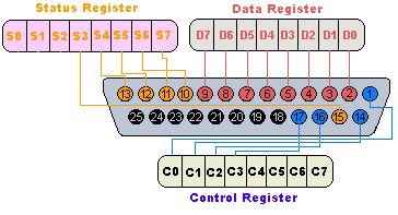
The lines are divided into three groups: data lines, control lines, and status lines. The black pins are connected with ground. As the name suggests, data is transferred over the data lines, control lines are used to control the peripheral and the peripheral returns status signals through the status lines. These lines are internally connected to the data, control and status registers. By manipulating the registers, one can read or write to the parallel port.
Each register has a unique I/O port address. For a typical PC, the base address of LPT1 is 888 (= 378 hex) and of LPT2 is 632 (= 278 hex). The data register resides at this base address, the status register at baseaddress + 1 and the control register at baseaddress + 2. Details about programming the registers can be found in any PC hardware book.
If the port is set to output mode, everything written to the data register will appear at the corresponding lines as voltages, and can be measured with a multimeter. For instance if we write 1 to the data register, pin 2 of the connector will be driven to a TTL high level of +5V. This way we can turn on and off any of the data lines. After this long introduction, the script that toggles all data lines of the parallel port is really simple:
while(1) {
  port_out(888,255); // set all data lines to +5V
  wait(-1);
  port_out(888,0);   // set all data lines to 0V
  wait(-1);
}
You can measure the voltage level with a multimeter between Pins 25 (Ground)
and 2 (Data0). Be aware that on some parallel ports, not all of the pins
18..25 are connected to ground.