
Normalmapping
shader
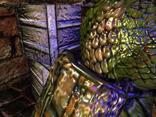
Fur
shader
Programmable shaders add a new dimension to graphics rendering by allowing the transform, lighting, and rendering functionality to be modified at runtime on a vertex and pixel basis. A shader is a small program that runs for every vertex, or every pixel that is rendered on the screen. It can control the vertex position, color and normal, the texture coordinates, as well as the pixel color and brightness, dependent on the influence of light, textures or lite-C variables. This gives the user a new level of dynamic flexibility over the way that pixels are rendered. Vertex and pixel shaders can be used to create realistic water ripples, render cartoon style, cover models with fur, or control the lava flow of a volcano (screenshots by users on the Gamestudio Shader Forum).
|
|
|||
|
Normalmapping
shader
|
Fur
shader
|
Shaders come in two flavors: vertex shaders manipulate mesh position vertices, pixel shaders manipulate texture pixels. The shader code is loaded into the graphics card memory and plugged directly into the graphics pipeline. Shader code is in assembly, however nowadays a higher level 'C' type language - HLSL - is used that is compiled down to the assembly and makes shaders much easier to program. HLSL uses the same syntax as lite-C. Pixel and vertex shaders can be defined as part of the material effect script, by using the VertexShader and PixelShader keywords. For learning shader programming, start with the Shader Workshop on the Gamestudio Download Page. Here's a quick overview only.
float4x4 matWorldViewProj : WORLDVIEWPROJ;
float4 vecTime;


void vs_flicker_red(
   in float4 iPos : POSITION,
   in float2 iTex0 : TEXCOORD0,
   in float2 iTex1 : TEXCOORD1,
   out float4 oPos : POSITION,
   out float4 oDiffuse: COLOR0,
   out float2 oTex0 : TEXCOORD0,
   out float2 oTex1 : TEXCOORD1)
   {
     oPos = mul(iPos,matWorldViewProj);
     oTex0 = iTex0;
     oTex1 = iTex1;
     oDiffuse.r = fmod(vecTime.w * 0.1,1.0);
     oDiffuse.g = 0.0;
     oDiffuse.b = 0.0;
     oDiffuse.a = 1.0;
   }


technique flicker
{
   pass p0
   {
     VertexShader = compile vs_1_1 vs_flicker_red();

   }
}
Shader programming is non-trivial and requires some knowledge in vector and matrix algebra. However, once a shader effect is defined in a proper way, it can be used by everyone without knowledge of its internal works. A good introduction into writing shaders for Gamestudio can be found at the end of the lite-C Workshops. The full shader language reference is contained in Microsoft's DirectX documentation. There are several books about shader programming. For an example how to write reusable shaders, look into the Shader library.
Recommended tutorials and books:
A library of standard surface and postprocessing shaders is defined in the include\mtlFX.c file and can be included in any project. For details see Shader library.
Shaders are a special kind of material effects. You should be familiar with the texture stage concept of DirectX for defining effects. Therefore, writing effects is only a matter for advanced users, although it's fun to try out the different render states and texture operators, and look which effects they produce on the screen. However, once an effect is properly written it can be used by anyone. In the following you'll find a brief overview over the elements of an effect, as well as some specialities (such as, special meaning of some names) when using effects in the Gamestudio engine. Please not that this overview is by far not sufficient to understand effects - the reading Microsoft DirectX9 Documentation is required.
Effects are split into three main sections:
Variable declarations - optional values that are set before rendering and then used in this effect, for instance textures, the world matrix, or lighting parameters.
Techniques and passes - they define how something is to be rendered, and include state information along with vertex and shader declarations.
Functions - optional shader code written in shader assembler or HLSL.
Variables are defined at the start of the effect file. You must specify a type and a unique name. You can then provide specific values depending on the type specifying the usage, user defined data and initial values. Example:
float4 diffuse : DIFFUSE = { 0, 0, 0, 1 };
float4 is the type (a floating point vector with 4 components), diffuse is the name. After the colon is a tag specifying the usage, in this case it is to be used as a diffuse colour. Finally the value is initialised to 0,0,0,1 (red, green, blue, alpha).
float4x4 matWorld : WORLD;
float4x4 matView : VIEW;
float4x4 matProj : PROJECTION;
This declares three matrices with the names matWorld, matView and matProj that will be used for the world, view and projection matrix during this effect. Those matrices are already predefined by the engine, and automatically set to the world, view and projection matrix of the object to be rendered.
A7.60 Variables can be shared among effects, using the shared type modifier. The engine allocates an effect pool for all shared effect variables.
Variables can have any name, but some variable names are predefined for accessing engine, material, or entity parameters. You'll find a list of all predefined variable names in the Effect Variables chapter.
An effect contains one or more techniques. Each technique consists of one or more passes. Each pass consists of a setting of one or more texture stage registers of the 3D hardware, and optionally a pixel or vertex shader that redefines the behavior of the stage. The object is rendered once for each pass, using the given settings.
If a certain technique does not work because the 3D hardware does not support the given texture stage states, the next technique from the effect is automatically selected. Therefore an effect should always contain a simple fallback technique for supporting old hardware. For example, to create a realistic rippled pond of water that reflects light, you begin with the first technique that renders the water, adds specular highlights, adds caustic textures, and applies light to the water in a single pass. If your hardware cannot render this technique in a single pass, a second technique might render the water, add specular highlights or caustic textures, but not apply light to the water.
A technique is defined with the keyword technique followed by an optional unique name, e.g.
technique BumpMapping
Techniques can have arbitrary names, but some names have a special meaning for the engine:
Within the technique you can define one or several passes which contain the actual state assignments. Every pass is an actual render process. A pass is defined with the keyword pass followed by an optional unique name, e.g.
pass one
Passes are executed in the order they appear within the technique. Within a pass you can set states to values or expressions. They are set in a very similar way as in the script, for instance:
ColorOp[0] = SelectArg1;

LightEnable[0] = true; // turn on light 0
ZEnable = true; // turn on depth tests
All the available states and options can be found in the DirectX documentation. So an example of two techniques, the second having two passes, could be:
technique FirstTechnique
{
   pass P0
   {
   // Set states here for pass 0
   }
}

technique SecondTechnique
{
   pass P0
   {
   // Set states here for pass 0
   }

   pass P1
   {
   // Set states here for pass 1
   }
}
Example for a simple texturing technique:
texture entSkin1; // Variable declaration

technique textureTechnique
{
   pass p0
   {
     Texture[0] = <entSkin1>;

     MinFilter[0] = Linear;
     MagFilter[0] = Linear;
     MipFilter[0] = Linear;

     ColorOp[0] = Modulate;
     ColorArg1[0] = Texture;
     ColorArg2[0] = Diffuse;
     AlphaOp[0] = SelectArg2;
     AlphaArg1[0] = Texture;
     AlphaArg2[0] = Diffuse;
   }
}
The texture is assigned to stage 0, then the filtering is set to bilinear. The texture is then modulated with the diffuse color by setting the color operators.
Passes can have arbitrary names, with the following exception (A7.60): If the first pass name contains the character sequence "_repeat", the pass is repeated for every skin of the model. After each pass the skins assigned to entSkin1..entSkin3 are incremented by 1. So if the model has 5 skins, the pass is repeated 5 times, with entSkin1 set to the model's first, second, third, fourth, and fifth skin in succession. This special method can be used to render an arbitrary number of skins, for instance for multitexture terrain with 4 or more textures. Example:
texture entSkin1; // tiled terrain texture with mask on alpha

//////////////////////////////////////////////////////////////////////

technique terraintex
{
  pass multitex_repeat11
  {
    AlphaBlendEnable = True;
    SrcBlend = SrcAlpha;
    DestBlend = InvSrcAlpha;

    Texture[0] = <entSkin1>;
    TexCoordIndex[0] = 0; // base texture coordinates for alpha
    AlphaOp[0] = SelectArg1;
    AlphaArg1[0] = Texture;

    Texture[1] = <entSkin1>;
    TexCoordIndex[1] = 1; // detail texture coordinates for RGB
    ColorArg1[1] = Texture;
    ColorArg2[1]= Diffuse;
    ColorOp[1] = Modulate2x;
    AlphaArg1[1] = Current;
    AlphaOp[1] = SelectArg1;

    ColorOp[2] = Disable;
    AlphaOp[2] = Disable;
  }
}
If "_repeat" is followed by two numbers as in the above example, the first number (1..4) is the skin to start with the repetition, and the second number (1..4) is the skin increment per pass. Example: if a model has 6 skins, a pass ending with "_repeat32" will repeat two times, the first time with the 3rd skin on entSkin3 and the 4th on entSkin4, and the second time with 5th skin on entSkin3 and the 6th on entSkin4. The first and second skin stay assigned to entSkin1 and entSkin2 during both passes. This way common skins, such as lightmaps or normalmaps, can be used for all passes. The number of the current pass repetition can be evaluated through the iRepeat shader variable.
The above example did not include any shader code - they are so-called Fixed Function Pipeline (FFP) effects. For detailed information on writing shaders on your own, please have a look into the Shader Tutorial.
The most common shader functions are contained in the code\default.fx file and can just be included in any shader. Use them for your own shaders! This not only makes the shader code much shorter, it also avoids errors and allows adjustments that automatically affect all shaders. For details see Shader includes. Examples for the usage of default.fx can be found in all shaders of the the mtlFX.c shader library.
That's what the engine passes to the vertex shader. The A7 vertex struct is defined in atypes.h. All geometry and model vertices use three UV coordinate sets for texture, lightmap/detail map, and shader tangents, in the following format:
typedef struct {
   float x,y,z;    // position
   float nx,ny,nz; // normal
   float u1,v1;    // coordinate set 1, for base texture
   float u2,v2;    // coordinate set 2, for light map or detail map
   float x3,y3,z3,w3; // coordinate set 3, for tangent or other purposes (A7.06 and above only)
} D3DVERTEX;

#define D3DFVF_D3DVERTEX (D3DFVF_XYZ|D3DFVF_NORMAL|D3DFVF_TEX3|D3DFVF_TEXCOORDSIZE2(0)|D3DFVF_TEXCOORDSIZE2(1)|D3DFVF_TEXCOORDSIZE4(2))